Galvanizing Settings
- General Overview
- Related Tools
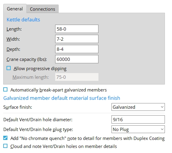
Length: The interior length of the galvanizing kettle. This information is referenced when the ![]() Check for kettle fit
Check for kettle fit![]() Allow progressive dipping
Allow progressive dipping
Note: If
Allow progressive dipping is on (checked), the AGA tool uses the Maximum length that is entered (below) when doing the
. Parametrics: Fabricator(). kettle_length
Width: The interior width of the galvanizing kettle. This information is referenced when the ![]() Check for kettle fit
Check for kettle fit
Parametrics: Fabricator(). kettle_width
Depth: The interior depth of the galvanizing kettle. This information is referenced when the ![]() Check for kettle fit is run using the Galvanizing Check Tool.
Check for kettle fit is run using the Galvanizing Check Tool.
Parametrics: Fabricator(). kettle_depth
Crane capacity (lbs): The maximum weight (in pounds) that the galvanizing crane can safely lift. This information is referenced when the ![]() Check for kettle crane capacity
Check for kettle crane capacity
Parametrics: Fabricator(). kettle_crane_capacity
Allow progressive dipping: ![]() or
or ![]() .
.
If this box is checked (
If the box is not checked (
), the
Parametrics: Fabricator(). kettle_max_progressive_dip
Maximum length: The effective length of the galvanizing kettle due to progressive dipping being allowed. This length might, for example, be approximately double the actual length of the interior of the kettle, since one procedure for progressive dipping is to galvanize half of the member, then galvanize the other half.
The
is on (checked). Parametrics: Fabricator(). kettle_max_progressive_dip
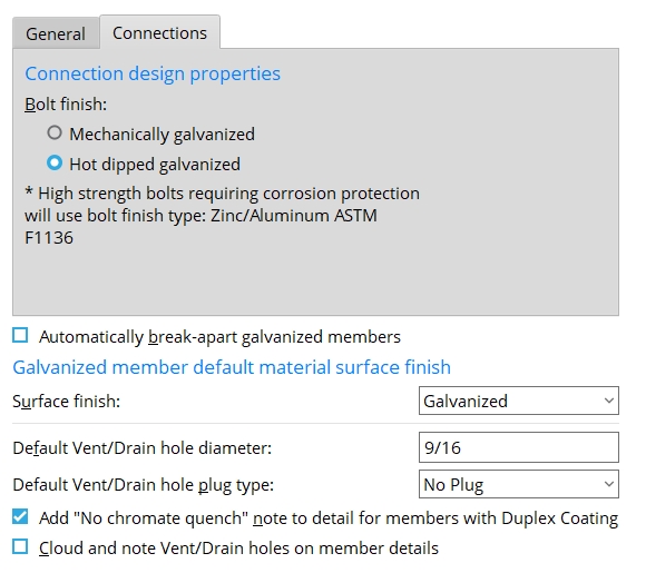
Bolt finish: Mechanically galvanized or Hot dipped galvanized. This applies when a member that has its Surface finish set to a Galvanized surface finish undergoes Process and Create Solids.
If
Mechanically galvanized is selected, the Finish of shop bolts and field bolts on Galvanized members will, by default, be set to Mechanically galvanized.
If
Automatically break-apart galvanized members: ![]() or
or ![]() .
.
If this box is checked (
on that same window. Assuming that you keep Break apart checked, when the member next undergoes Process and Create Solids it will be broken apart into different members, so that each member can be galvanized separately. Only non-welded materials will be broken apart. Welded materials will remain attached to the member main material. If the box is not checked (
Surface finish: Galvanized or Duplex coating.
Galvanized sets the Surface finish to Galvanized for all materials of members that have their Surface finish set to a Galvanized surface finish and which subsequently undergo Process and Create Solids.
Duplex coating does the same as Galvanized, except the Surface finish is Duplex Coating, which is a special coating that allows galvanized steel to be painted.
Default vent/drain hole diameter: The diameter of vent/drain holes. On the Hole Edit window, the value entered here is the default Hole diameter that is entered, automatically, when you add a hole whose Hole type is Vent/Drain.
Note: Vent/drain holes that are added automatically on handrail custom members do not use this value. The Auto hole diameter for a handrail is a calculated value that is based on the I.D. (inside diameter) of the pipe or tube.
Default vent/drain hole plug type: No plug or Zinc plug or Plug weld or Aluminum or Epoxy. This is the Plug type of the vent/drain hole.
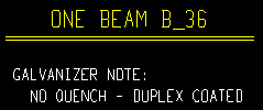
Add "No chromate quench" note to detail for duplex coated members: ![]() or
or ![]() . This applies when a member's Surface finish is set to a Galvanized surface finish and undergoes Process and Create Solids, then undergoes Detail Members.
. This applies when a member's Surface finish is set to a Galvanized surface finish and undergoes Process and Create Solids, then undergoes Detail Members.
|
If this box is checked (
If the box is not checked (
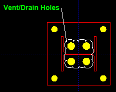
Cloud and note Vent/Drain holes on member details: ![]() or
or ![]() . This applies when a member has submaterial with vent/drain holes. To get the note on the member detail, the member must have its Surface finish set to a Galvanized surface finish and have undergone Detail Members.
. This applies when a member has submaterial with vent/drain holes. To get the note on the member detail, the member must have its Surface finish set to a Galvanized surface finish and have undergone Detail Members.
|
How vent/drain holes are called out on a member detail when this option is checked ( |
If this box is checked (
If the box is not checked (
( in Detailing Symbol Settings and they are non-standard hole sizes. The vent/drain holes will not be called out with a pointer to a label that reads "Vent/Drain Holes".Also see: The vent/drain holes that are detailed in the example above were originally specified in the Vent/Drain Holes tab on the Base/Cap Plate Options screen.


|
|
OK (or the Enter key) closes this screen and applies the settings.
Cancel (or the Esc key) closes this screen without saving any changes.
Reset undoes all changes made to this screen since you first opened it. The screen remains open.
- Surface Finishes (Project Settings)
- Surface Finish (Member edit window)
- Bolt Finish (Bolt edit window)
- Galvanizing Check Tool

